More than half a year ago Dave Campbell [1], Luis Abreu [2] and I had a discussion [3] about the 1px line width problem in Silverlight and WPF [4]. A short summary of the problem when drawing lines with 1px and using an anti-alias effect:
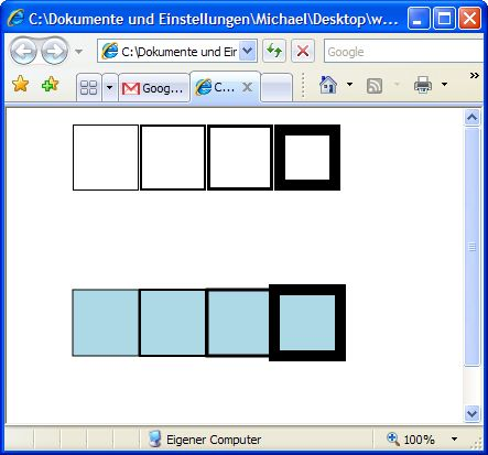
The example above is built with rectangles in the first line of boxes. The second line is done with the Path XAML element. The first row has a stroke thickness of 1px, the second 2px, 3px,... What you will see is that using a path or line and a odd pixel number for the stroke thickness the anti-alias effect will render a 1px wider stroke with a little transparent border. The other correct difference is that the line for the path is always centered where the border for the rectangle will always grow to the middle - and that is the real problem. If you have a stroke thickness of 1px and you want to render it at the center of a line you will have to render 0.5px to the left and 0.5px to the right. The result is the transparent look of odd pixels.
If you are thinking about creating an Silverlight [5] application that will look like a real Windows application you have to render a lot of lines and boxes. I had an email discussion with Scott Guthrie [6], Mike Harsh [7] and Ashraf Michail [8] and don't want to deprive you this:
Mike writes: "...] Next is the missive on why vertical and horizontal lines are hard in a vector engine. As you were part of the discussion in the forums, I'm sure you've seen this post on the subject: [http://www.wynapse.com/Silverlight/Tutor/Silverlight_Rectangles_Paths_And_Lines_Comparison.aspx [9]
There are two things to keeping mind here, pixel boundaries and compatibility. The way strokes work is by using a geometry expansion algorithm to calculate the area to fill with the brush specified by the Stroke property. For a 1px stroke, the expansion is 0.5px inside the shape and 0.5 outside. This means that your pixel boundary aligned shape is no longer aligned. The fix for this is to shift your shape by 0.5px using Canvas.Left and Canvas.Top to make it align again.
As you've noticed Rectangles tend to do the right thing more often. Rectangles are special because we always know the lines will be horizontal and vertical (unless a skew, rotate or arbitrary matrix transform is applied) and we know the exact height and width so the expansion algorithm will not make the shape larger than the rectangle's height and width.
It is still possible to get a rectangle to behave oddly by positioning it on a non-pixel boundary or scaling it to be less than 1px.
The question is why don't we add some special case logic to know when a line element is horizontal or vertical or when a segment in a path is horizontal or vertical? We could do this, but then the Silverlight rasterization engine would behave differently than the WPF engine and this would introduce an incompatibility in the way XAML is rendered.
Finally you should only use a line element if you need an <HR> type effect. Using a Line to make a rectangle won't always give you the correct results since the rendering engine doesn't know that these 4 elements are associated. This means you can get inconsistent seams at the corners. If you've got connected line segments use a rectangle, polygon or path.
Here are the recommendations for drawing single pixel straight lines:
1. Always use a rectangle if you can 2. Only use a line element if you need an <HR> type effect.
3. Make sure everything is aligned on a pixel boundary
4. Only apply integral scale and translate transforms
Here is a version of the XAML from the blog post above with proper pixel aligned boundaries:
<Canvas xmlns="http://schemas.microsoft.com/client/2007" Height="100" Width="150" Background="white" Canvas.Top=".5">
<Rectangle Canvas.Left="50" Canvas.Top="5" Width="50" Height="50" Stroke="Black" StrokeThickness="1" /> <Path Canvas.Left="0.5" Canvas.Top="0.5" Stroke="Black" StrokeThickness="1" Data="M20,20 L70,20 L70,70 L20,70z"/>
<Line Canvas.Left="0.5" Canvas.Top="0.5" Stroke="Black" StrokeThickness="1" X1="80" Y1="20" X2="130" Y2="20" />
<Line Canvas.Left="0.5" Canvas.Top="0.5" Stroke="Black" StrokeThickness="1" X1="130" Y1="20" X2="130" Y2="70" />
<Line Canvas.Left="0.5" Canvas.Top="0.5" Stroke="Black" StrokeThickness="1" X1="130" Y1="70" X2="80" Y2="70" />
<Line Canvas.Left="0.5" Canvas.Top="0.5" Stroke="Black" StrokeThickness="1" X1="80" Y1="70" X2="80" Y2="20" />
<Path Stroke="Red" StrokeThickness="2" Data="M35,40 L115,40 L115,85 L35,85z"/> <Path Stroke="Blue" StrokeThickness="1" Data="M5.5,45.5 L60.5,45.5 L60.5,95.5 L5.5,95.5z"/> <Line Stroke="Blue" StrokeThickness="1" X1="90.5" Y1="45.5" X2="145.5" Y2="45.5" />
<Line Stroke="Blue" StrokeThickness="1" X1="145.5" Y1="45.5" X2="145.5" Y2="95.5" />
<Line Stroke="Blue" StrokeThickness="1" X1="145.5" Y1="95.5" X2="90.5" Y2="95.5" />
<Line Stroke="Blue" StrokeThickness="1" X1="90.5" Y1="95.5" X2="90.5" Y2="45.5" />
</Canvas>
I hope this helps,"
Generally, the way to determine how something will appear when rasterized involves remembering the following rules:
<li>Integer pixel coordinates are located at the top left corner of a pixel</li> <li>Anti-aliasing is accomplished using a box filter located at the center of the pixel</li> <li>Strokes expand in by half the strokethickness and out by half a strokethickness then follow the fill rules defined by 1+2.</li> Rule #1 is desirable for allowing rectangular fills to map 1-1 onto pixels by default and rule #2 ensures symmetry of rounded shapes like rounded rectangles.
Strokes on rectangles are special cased to use the inset pen (goes inwards by the full strokethickness) instead of going half way in either direction. The inset pen option is not exposed on other geometries currently. The reason rectangle stroke was special cased was for a UI design convenience. Generally, UI requires borders on rectangles to be inset.
If you want to draw several separator lines in your UI that you would like to be aligned to pixel boundaries, my recommendation would be to use a thin filled rectangle element to draw your line.
Thanks to Ashraf for those rules!